<< p1 | p2 | p3 | p4 | p5 | p6 | Ode to Gertie | Notes | Comments | Bibliography >>
The DRTE Computer (page 4)
The Binary/Decimal and Decimal/Binary Converter
Within the computer, all instructions and numbers appear as binary numbers. Hence a method is needed that will convert the decimal nature of inputs to machine readable binary numbers, Similarly, binary outputs from the computer must be converted to the number system the user will feel most comfortable in, the decimal system. Usually the conversions are carried out by means of software routines. However, conversion sub-routines take up memory space and tie up the Arithmetic Unit. For Florida the optimum use of memory was essential because of the prohibitive cost of core memory. Florida decided to implement the conversions through special hardware. This method would be faster than using sub-routines and it would also free up the Arithmetic Unit.
There are several algorithms one can use to carry out the conversions. The choice of algorithm depends on how efficiently, in time and memory, it can carry out the conversion. In a DRTE report in 1955, Florida(1955) explored the various algorithms one could use to effectuate the conversions. The key problem was to find the fastest algorithm that could be easily translated, both in economic and technical terms, into electronic circuitry.
Instead of repeated divisions or multiplications by ten Florida used an algorithm that simply involved shifting to the right or left (which are equivalent to multiplication or division by 2). To carry out the conversion from decimal to binary, the decimal number from the Flexowriter was coded into pseudo-binary format using octal groupings. Each decimal digit was represented by an binary octal grouping. For example, the decimal number 369 was automatically coded to 0011:0110:1001.This was carried out by the "Input Organ" that interfaced the Flexowriter to the Converter. The reverse process was carried out by the "Output Organ". This intermediate binary coded version of the decimal number was used to store the number while the conversion was going on. However, this coded form added some complications to the left and right shifting algorithms (Florida,1955). Because of the nature of the octal grouping of decimal digits the left and right shift algorithms had to be modified by what Florida called the "excess 3 code" and "excess 6 code" respectively, in order to give the correct result. (Comment 11)
In order to carry out these shifts Florida developed an eight-stage register based on eight P-N-P-N trigger circuits and a variety of logical elements (AND, OR, Inhibiting , and Inverter gates) (see Fig. l0). This register turned out to be extremely versatile. In addition to being used in the conversion unit, this versatile register was the fundamental building block of the computer's Arithmetic and Control Units. The register fulfilled six basic functions: shift right, shift left, count up, count down, parallel shift, and set zero (Florida,1959),
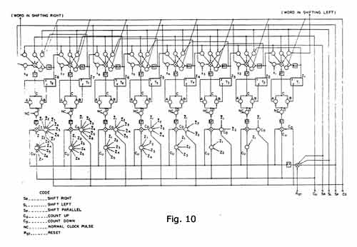 |
| Click for a larger view |
It was George Lake's task to turn Florida's conversion algorithms into workable electronics (Lake,1960). Information from the Input Organ was transmitted serially to the converter. However, in order to increase speed, information from the converter was parallel-shifted to memory. Similarly, information was parallel-shifted from memory to the Converter and then serially to the Output Organ. The Converter ~ contained a total of 128 trigger circuits which was 20% of the total number used in the computer. Lake justified this high percentage on the grounds that it increased the overall efficiency of the system.
"While this may seem excessive for what is essentially an auxiliary unit it is felt that the savings in conversion time and memory space for input-output routines will be more than offset any additional cost"(Lake,1960:49).
There is always the problem of interfacing the speed of conversion with the speed of the input or output devices.
The longest operation is floating point decimal to binary conversion which requires a maximum of 334 digit periods. If each digit period is 5 microseconds, the total time is 1.67ms. The photoelectric tape reader that will feed the converter, via the input organ, reads 600 decimal digits per second. This corresponds with a digit spacing of about 1.67 ms. Since at least one space character will follow each operand the total time available for the conversion is about 3.34 ms. This permits the converter to complete its operation between the time the last digit of one operand is read and the time the first digit of the next operand is read, making it unnecessary to stop the tape reader between operands.
On the output side, floating point binary to decimal conversion requires a maximum of 1.66ms. It is proposed initially that the converter drive the flexowriter via the output organ for printing out the converted operands. The flexowriter types at a maximum speed of 10 characters per second or 100 ms per character. Each operand to be printed out is preceded by a case shift character that requires 150 ms for the flexowriter to complete. Thus, by the time the initial case shift is complete, conversion of any possible operand is complete and the operand is ready to be printed a digit at a time"(Lake,1960:49)
It was a stroke of good luck that the conversion speed matched the operation of the flexowriter. However, one can quickly see that the potential for bottlenecks between the converter and the input and output devices could have been significant. How would the converter have handled data coming in from a fast card reader? The way the system was designed, there was more flexibility in increasing the speed of the input and output devices than there was in constantly rewiring the converter. Here we see another example of the flexibility lost when software tasks are incorporated into the hardware.
 |
|
|
 |
|
|
The Control Unit
The Control Unit coordinates the operation of all the parts of the computer system. It is the central nervous system of the computer. In the case of the DRTE computer the flow of information to and from the Control Unit is given in Fig. 11. The design and construction of the Control Unit was a result of a close collaboration between Florida and Cobbold. tike the Converter Unit, the Control Unit also made use of the multipurpose register developed by Florida (see Fig. 10). (Comment 12)
 |
|
|
In order to increase the speed of the machine information was parallel-shifted to and from the Control Unit. The basic schematic of the Control Unit is shown in Fig. 12.The two essential registers in the Control Unit are the Program Counter (P.C.) and the Command Word Register (C). The P.C. register governs the automatic sequence control process. This register contains the address of the instruction which is about to be executed. Hence it only has to be large enough to accommodate the largest core memory address. Therefore a P.C. register of 10 bits was sufficient to address a core memory 1024 words. The C register acted as a temporary location for the command word being executed. Because of the 3-address system the C register is divided into four 10 bit sections. In addition to the above two registers, the Control Unit also contained a 10 bit register (K) as temporary storage for the contents of P.C., five 10 bit index registers, a 10 bit parallel adder, and a unit to decode the Order Code dart of the Command Word. (Comment 13) (Comment 14)
 |
|
|
The basic control cycle (those sequence of operations carried out by the Control Unit between the execution of two simple Arithmetic Unit commands) was divided into six 10 microsecond periods (Cobbold,1959):
| Period |
Operation
|
| 1. | Acknowledge the end of operation pulse from the Arithmetic Unit |
| 2. | Memory write cycle: write the answer obtained by the Arithmetic Unit into the address given by W part of the Command word. |
| 3. | Memory read/write cycle: read out a new Command word from the Memory. |
| 4. | Memory read/write cycle: read out the first operand. |
| 5. | Memory read/write cycle: read out the second operand. |
| 6. | Initiate the next Arithmetic Unit operation |
 |
|
|
 |
|
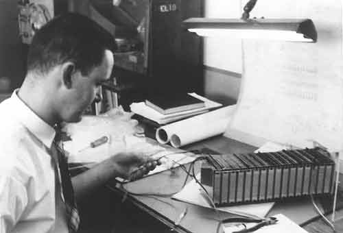
A drawer for PC cards. It could be any one of the arithmetic, control unit or converter drawers. |
<< p1| p2 | p3 | p4 | p5 | p6 | Ode to Gertie | Notes | Comments | Bibliography >>